Knowledge Base

Flow Rate Ratio is obtained by dividing an MFI value obtained by use of a higher Mass with one obtained with the use of a lower Mass.
Flow Rate Ratio (FRR) is commonly used as an indication of the way in which the rheological behaviour of a thermoplastic is influenced by the molecular mass distribution of the material. Since polymers are made up of varying lengths of polymer molecular chains, the length of the chain determines the flow characteristics. Since it is difficult to control the exact chain length during polymerisation, the resulting mix or distribution of chain lengths (long and short) also known as the molecular weight distribution, affects the resulting flow properties. This molecular weight distribution is also an important contributor to the physical and mechanical properties of the resulting polymer amongst other items.
According to ISO 1133 (2011), Flow Rate Ratio (FRR) is calculated by taking a mean of Melt Flow Rate measurements using low gravimetric weight (e.g. 2.16kg) and a mean of Melt Flow Rate measurements using a higher gravimetric weight (e.g. 10kg). Dividing one by the other gives a ratio:
FRR = MFR (190 °C, 10kg)/MFR (190 °C, 2.16kg)
Similarly, the ratio can be derived by using the melt volume rate instead of the melt flow rate,
FRR = MVR (190 °C, 10kg)/MVR (190 °C, 2.16kg)
Melt flow index (MFI) or Melt Flow Rate (MFR) is a measure of a given polymers’ flow characteristics also known as the Rheological properties in the molten state under a known applied pressure. The MFI value quoted on many datasheets refers to the amount of polymer that is extruded through a known given orifice (die) and expressed as quantity in g/10 mins or for Melt Volume Rate in cm3/10mins.
The basic principle of MFI is a simple one. Polymer resin, flake or powders are introduced into a heated barrel at the bottom of which is a die with known bore diameter. The standard bore die size is 2.095mm in diameter. It is important to ensure that when the polymer granules are introduced to the barrel that all entrapped air is removed by tampering down the granules, as any air entrapment will give erroneous results. Once the bore is full a piston is placed in the barrel with a known dead weight on top of it. For very basic machines the Extruded samples are cut and the weighed from which the MFI value than calculated.
Why is it Important ?
The viscosity at infinite slow shear is called zero shear rate viscosity (η0) which is essentially what is obtained using the lowest gravimetric weight during MFI. The observed shear thinning of polymer melts is caused by the disentanglement of polymer chains during flow. Polymers with a sufficiently high molecular weight are always entangled and oriented randomly at rest. When sheared, they begin to disentangle and to align which causes the viscosity to drop. The degree of disentanglement will depend on the shear rate. At sufficiently high shear rates the polymers will be completely disentangled and be fully aligned. At this stage, the viscosity of the polymer melt will be independent of the shear rate, i.e. the polymer will behave like a Newtonian liquid again. The same is true for very low shear rates; the polymer chains move so slowly that entanglement does not impede the shear flow.
References:
ISO 1133 – First edition 2011-12-01
Ray-Ran MFR300: Advanced Melt Flow System Introduction

Was this useful?
Related Products
-

Ray-Ran MFR300 Microprocessor Melt Flow System
Ergonomic and easy to use - with sophisticated touch screen electronics - the MFR300 melt flow indexer is packed with features to verify and validate sample materials quickly and efficiently.

-

Ray-Ran MFR200 Microprocessor Melt Flow System
The Ray-Ran MFR200 Microprocessor Melt Flow System measures the melt flow index of thermoplastic materials to ASTM D1238 and ISO 1133, using an automated cut device for improved repeatability. Suitable for plastics manufacturers, compounders and quality control laboratories.
-

Ray-Ran MFR100 Manual Basic Melt Flow System
Molten Polymer is extruded through a controlled Die and using the time taken to extrude the Melt Flow Rate or Melt Mass Flow rate in g/10 minutes can be determined
-

Ray-Ran Apparent Bulk Density Apparatus
Accurately measure the apparent bulk density of powders, granules, and other divided solids using Ray-Ran's Apparent Bulk Density Apparatus. Each model is designed to meet the specific requirements of ASTM D1895 (Methods A, B or C) or ISO R60.
FAQs
-
Flow rate ratio is the comparison of the flow rates of two fluids or the same fluid under different conditions.
-
It helps in understanding fluid dynamics and optimizing processes in various industries.
Related Articles
-
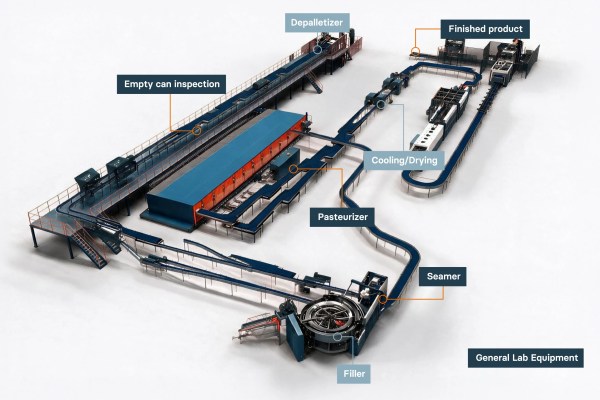
Explore every stage of the modern beverage can filling line with our interactive beverage can filling process map. From can depalletizing and rinsing through to filling, seaming, pasteurizing, and palletizing, each step in the process demands precision, consistency, and quality assurance. By hovering over each stage in the diagram below, you can discover the most…
-

Key terms Term Definition Double seam The mechanical interlock that joins a can end to the can body; the primary barrier against leaks. Non-destructive testing Inspection that measures a can without cutting or destroying it, allowing higher inspection frequency. Destructive teardown Traditional seam inspection that cuts the can apart to measure internal seam features by…
-

Beverage can manufacturing is a high-speed, high-volume business. A single line can turn coil into thousands of beverage cans a minute, through cupping, drawing and ironing, trimming, decorating, internal coating, necking, flanging and palletizing. Every one of those steps must stay within tight tolerances, because a small drift multiplied across a fast line becomes a…
